 |
ITC Bridge > Instrumental Transcommunication (ITC) > Frequency Sweep | Radio Sweep Tuning > Dollar Tree $1 sweeper breakthrough ! |
| |
ITC Bridge > Instrumental Transcommunication (ITC) > Frequency Sweep | Radio Sweep Tuning > Dollar Tree $1 sweeper breakthrough ! |
| ITC Bridge and iDigitalMedium.com are now VARANORMAL.COM Please visit: https://www.varanormal.com This site does not allow new registrations, and is now an online archive of a decade of Paranormal and ITC (Instrumental Transcommunication) experimentation from 2007 - 2016 We thank you for a wonderful decade! ~ Keith Clark & Ron Ruiz |
| Moderated by: Vicki Talbott, Keith Clark, ArizonaEvp | ||
| Author | Post | |||||||||
|---|---|---|---|---|---|---|---|---|---|---|
|
Slider2732 Member
|
During a visit to our local Dollar Tree store, I was surprised to find some really quite good radio's, for $1. What can you expect for such a small sum ? Well, headphones included, for a start. Sweepable FM band radio. A flashlight ! with its own button on the unit. A good reception. Takes just 2xAAA batteries :D Seemed a great candidate for making a sweeper out of. I bought 3 or 4 and walked out of the shop with a smile! As things were, as with any sweeping radio, it would sweep upward til it found a good strength station and then stop sweeping. Pressing the sweep button again made it go a little further and stop again when it got to another station. Decided to take it apart and see what was what. The chip inside is a Silan SC1088 - datasheet here: http://www.alldatasheet.com/datasheet-pdf/pdf/86814/SILAN/SC1088.html Seems it's FM and AM capable...even better. Quickly realising the 'Mute' input on Pin 1 was readily negated, that was the first thing I did. It required running Pin 1, via a resistor to the +3V. A bit of experimentation with a 1k variable pot resulted in a situation where the sweep can be silent of received station signal or up to full signal reception as it sweeps...a handy enough feature. Next stage was to get that sweep to reset back to the start. There is a 'Reset' button on the unit, but of course we wish to do this automatically at the end of the sweep. Instant thought was a triggered system, something that would click in after a timed interval. Our friend the 555 timer seems very well suited. However, these devices usually start to work correctly at 4.5V, bit of a dilemma. Several other chips datasheets were looked at, anything with Scmitt triggers especially, but all started at +5V or were chips I didn't have. Next, I thought about CMOS versions of the 555. I had a TL555CP - excellent! these start to run at 2V and can be supplied with a lot more voltage if required. So, for 6hours today I experimented with the whole setup. First, the flash rate was too quick and didn't quite relate to online calculation guides of Duty time etc, but eventually I got it to work on an approximately 8 seconds rate, the time it takes the unit to scan through the whole FM band  Integration of the pulse of reset to the button that normally resets took up most time. Eventually, it was realised that there was an issue with the radio circuit picking up interference from the 555 when the 555 was supposed to be idle and causing a cancelling of radio reception at best. A diode on the 555 output fixed that ! Now, the radio scans around at 8 seconds time spans AND the audio can be heard as it does so :D Quite the set up for something measuring about 1.5" by 1" and 2XAAA battery powered. Audio will follow, but here's a pic of the prototype circuit.  |
|||||||||
|
Slider2732 Member
|
BTW, I do apologise for the awful picture there...with all this gadgetry around I don't have a decent pair of Alkaline AAA batteries for the power hungry camera  The radio works great with whatever is thrown into it (all day with the 555 chip running too and on Sunbeam 8 for a $1 AAA's, guess where I bought them hehe). |
|||||||||
|
joecioppi Moderator 
|
Slider, This SC1088 is the same chip as the old Philips TDA7088T and is the very same receiver I use in my Joe's Box. I use two TL555 timers to drive the tuner "scan" button and the "reset" button. I have rate controls for scan speed and sweep width as well as volume/power. I use an LM386N audio amp chip with a 2inch speaker. I use 3 AAA cells and still stay within the receiver chip max rating. When you couple the output to an amp from this circuit's earphone jack you need to use an audio coupling transformer such as a mini 400ohm to 400 ohm unit. The earphones are the load for the audio driver transistor and you need to substitute the primary winding for the earphones. joecioppi |
|||||||||
|
Slider2732 Member
|
Thanks Joe, interesting information there. My original sweeper built in March did drive a .25W loudspeaker with a 386 (configured x100 gain with the capacitor on Pins 1 and 8 method) and this current circuit might well end up amplified. Smiled as I read the familiar parts list in your box design...different folks building similar designs eh The SC1088 being at $1 would be reason enough to start with just the chip, but the fact that it comes with a whole circuit around it, earphone jack, earphones, housing and battery compartment is quite amazing. Here's a link to some audio, as the sweeper scans and resets: http://www.filefreak.com/pfiles/76779/DollarTree.mp3 Currently the reset time is at 8 seconds, but it's easy enough to use the small pot to increase and decrease. One good feature about these SC1088's is the effect of fitting an audio level pot between Pin 9 (bottom right) and +V. The trimming allows full audio scan down to no audio heard as it scans. Not really sure what the point of the trim is lol, but if totally negating terrestrial broadcasts is an aim, then there's its use. Is that like the sweep width on yours ? I'm having trouble getting a good 99/1 reset though. As you might hear, the duty cycle is about 60/40. I use an LED to indicate sweep and reset taken off Pin 3 of the Astable 555. Tried the usual formula for working it out but for some reason things don't quite match up. The 10uF capacitor isn't new though so I might replace it and see if that improves things with charging/draining. Last edited on Oct 7th, 2008 07:59 AM by Slider2732 |
|||||||||
|
joecioppi Moderator
|
Slider2732 wrote: Thanks Joe, interesting information there. My original sweeper built in March did drive a .25W loudspeaker with a 386 (configured x100 gain with the capacitor on Pins 1 and 8 method) and this current circuit might well end up amplified. Smiled as I read the familiar parts list in your box design...different folks building similar designs eh |
|||||||||
|
Slider2732 Member
|
OK, I see now about Pin 9 and would think it's bad practice. The same batteries are in the unit though as when I began all this and nothing seems to have been harmed. Must be a few hours of tests so far. Being a variable resistor i'd think it would still place any load onto the resistor and hence battery life not component life would be the issue. I could very well be wrong...and I don't mind being told that Solved the 99/1 duty cycle problem. I read somewhere about putting a diode in parallel with R2 on the 555 (Pins 6+7). Doing so fixed the issue, so that now there is a brief blip to reset and rescanning takes place again. Simple enough fix. We'll have to trade schematics ! |
|||||||||
|
sparks Member 
|
Hi Joe, Slider, Thought Id mention Ive done some work on a Box using a TDA7000 FM receiver chip. It can be configured to mute in between stations, but needs an external sweep waveform to push it along - unlike the TDA7088T with its self running scan function. The setup didnt work too good here, as it suffered from severe intermod due to me living not far from all the FM transmitters for our city. Gone back to AM sweep design using the RF board extracted from a 12-469, driven by sweep gen. Still working on the design for that, as Id like to emulate a random mode akin to Franks Box. Joe, I heard a podcast where you were talking about information flowing back to the present from the future, allowing answers to be received to questions before theyre asked. Ive thought something similar in relation to the temporal flexibility that must be available to other dimensions, and would account for reverse messages too, as they could send a normal message in a negative temporal direction, which would appear as reverse to our (positive direction only) time flow. regards from "down under", JEFF |
|||||||||
|
joecioppi Moderator
|
Hey Slider, here's my schematic.... 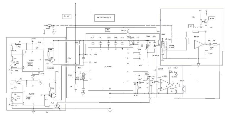 joecioppi |
|||||||||
|
Slider2732 Member
|
Thanks Joe Only got a small monitor here, but can follow what's going on. Do the transistors on the outputs of the 555's also negate the 'pop' spike sound, often heard as a 555 changes state ? I managed to minimise that effect using a 104 ceramic capacitor and the diode to the former Reset switch of the radio (while there seemed to be a problem if the diode wasn't in place). I was probably lucky with this version of CMOS 555 though, it apparently generates less output current. A probable bane for many circuits, but for this simple trigger operation the less current is probably the better. I haven't been able to do a schematic yet, my circuit is basically a hack and so the radio part is what's been altered. The basis though is the 555 to time a Reset of scan and the Mute bipass. As a 4.5V circuit, your ideas there seem logical and functional, makes me wonder if simply adding another battery would have simplified all the late nights on mine lol ended up removing some ideas and yet the unit does what i'd intended, as somewhat of a trainee in circuit mods. Thanks for posting it |
|||||||||
|
joecioppi Moderator
|
Slider, Here's a website dedicated to the dollar radio...even has a typical schematic showing the usual earphone output transistor. joecioppi http://www.hanssummers.com/radio/poundshop/index.htm Last edited on Oct 9th, 2008 04:46 PM by joecioppi |
|||||||||
|
Slider2732 Member
|
That's superb, really glad more people have been down the route of hacking these. At $1, they deserved a bit of a play with. Increasing the output and the other tricks they mention is great news...will certainly be trying out those mods. In the 1970's one of my brothers sent a small radio off to a relative of ours for fixing. Time passed and he didn't receive it back. We asked of it for a few years at family gatherings. Never knew what happened to it and it's one of those small memories of life. Getting inside these things is a bit of a reminder of that. With us pushing these into possible Paranormal useage, it seems it's a time honoured and interactive route in more than one sense Last edited on Oct 10th, 2008 10:00 AM by Slider2732 |
|||||||||
|
Slider2732 Member
|
Oh, btw sparks, the random mode of Frank's is something I didn't know of. Does the radio jump in at any stage of scanning and 'release' audio as a snippet ? Such a thing would fall along similar lines as the speech chip idea I was thinking of recently. Cyclic scanning, only pushed to output by a seemingly random event. In the case of the speech chip, it's hoped a spirit may be able to influence that timing, by selection of a speech word, in a way that would then be comprehensible to the living listener. While spirit time is apparently non structured, a whole phrase could be constructed that sounded real time. In the case of the radio, cyclic sweeping and then seemingly random output would be configured as tonal useage by the spirit. It's hoped that contained within the broadcasts would be elemental sonic traits that spirits already use when shaping for EVP...white noise, random background environment pressures. The two things appear broadly similar and I was wondering if Frank's devices use transistor noise spikes within developing the random time periods ? Where's Frank ? lol Last edited on Oct 10th, 2008 10:11 AM by Slider2732 |
|||||||||
|
sparks Member
|
Hi Joe, Slider, As far as I know (disclaimer here, as I dont have a Franks Box) ... Franks Box (in random mode) moves around while outputting raw audio (and introduced white noise). There is no squelching action or gated output in response to signals, unlike your design that scans in stealth mode until it receives a valid signal. Therefore the resultant audio (from Franks) would be a continuous audio stream with signals passing quickly in and through the passband of the receiver's selectivity response. In regards speech chips, Frank did experiment with using a Speakjet chip fed with random voltages into its serial port, and did get (I think) intelligent responses. In this case, the random voltage was derived from a noise transistor (as is in his Box). So this implies the noise structure seemed to be modified so that the speech chip received correct ascii commands to output meaningful phoneme strings to form words. If this is so, then it implies that random (quantum) event voltages are able to be modified interdimensionally. In regards the actual formation of voice messages via snippets, I heard a podcast which featured Rick Moran, who was saying his analysis of modified snippets indicated that the message was sandwiched in the middle of the broadcast snippet with a short period of silence at either side of the message. This would imply the message and the snippet are 2 different entities. Dont know if Rick's observation on this is accurate or not. Can you validate this Joe? regards, JEFF P.S: Apologies to Frank if Ive got any of my interpretations of his Box incorrect. |
|||||||||
|
joecioppi Moderator
|
Quote: " In regards the actual formation of voice messages via snippets, I heard a podcast which featured Rick Moran, who was saying his analysis of modified snippets indicated that the message was sandwiched in the middle of the broadcast snippet with a short period of silence at either side of the message. This would imply the message and the snippet are 2 different entities. Dont know if Rick's observation on this is accurate or not. Can you validate this Joe? " Hi Sparks, An un-muted scan allows inner station noise through ( that is random in nature) that contains message material. Franks box has been described as injecting noise or mixing noise, but it only plays radio static received between stations and the strong stations suppress the static noise born info. The louder message is selected from broadcast vocals by random tuning voltage derived from filtered transistor junction noise. Two sources are at work simultaneously. I believe the intelligence is in the random nature of either source(static and random tuning of broadcast stations). I believe the SpeakJet chip input is an A/D that generates random code commands to trigger the internal synthesis of words. The sense of those messages comes from the random nature of EMF noise fed into the A/D. joecioppi |
|||||||||
|
sparks Member
|
Hi Joe, I should have clarified that Ricks' analysis was on one broadcast snippet, where there was an embedded message inside the middle of it, and a small padding of silence each side of the embedding. Not too disimilar to the metamorphosis of voices Ive heard on EVP, where an announcers voice has been altered to say something other than what he originally said. The Speakjet chip used in speakjet "boxes" usually uses a PIC chip to interface the environment to the speakjet serial input, much akin to an A/D function, but where specific ascii commands are outputted to the speakjet i/p in response to environmental emf changes that are sensed by the front end of the PIC. Franks trial involved random analog voltage directly fed into the speakjet serial port, and sometimes sensible speech was outputted, so this sort of indicates that the random voltage was sometimes correlated to simulate the correct ascii commands and at the 9600 baud rate as well. The speakjet has a predefined range of ascii commands required for phoneme output as well as baud sync, length, pitch, etc. Ive got a speakjet chip, and am in the process of learning PIC programming. regards, JEFF |
|||||||||
|
Slider2732 Member
|
However, and this is something I discovered by accident. Feeding a chip with the wrong info can give the right results. I have a small game I built, using a very common 74161 and a few LED's. If I put unfiltered wall wart +3V to it, the 74161 becomes erratic, spinning the led outputs all over the place. Pushing a stop button hangs the output on whatever LED it was up to....forming a game where the idea is to land it on the green LED. Have attached a pic of that micro game. Likewise, i'm currently building up a multi-function paranormal device (Para-meter) containing the modified scanning radio and an AMD 8255 from 1981. These were the routing/in/out assistance chips for the Intel 8051 processor. I had about 30 of them from old arcade PCB's and set about seeing if any other use could be found for them. By datasheet study of in/outs and some admittedly random experiments, I found that these chips become amazingly responsive to static electricity and the paranormal version of EMF fields! In addition, a reliable single wire touch sensor is another use for them. They work right down to +3V single supply (both Intel and AMD versions), ideal for my 3.6V Ni-Cd projects. Have attached top and bottom views of this current one too. Attached Image (viewed 7353 times): Last edited on Oct 11th, 2008 09:42 AM by Slider2732 |
|||||||||
|
Slider2732 Member
|
8255 front Attached Image (viewed 6534 times): |
|||||||||
|
Slider2732 Member
|
8255 rear Attached Image (viewed 6693 times): Last edited on Oct 11th, 2008 09:45 AM by Slider2732 |
|||||||||
|
ourobouros2k2 Member
|
Just curious, sparks, what pin or wire drives the scan function on the .469? I have a linear scan circuit that I found in the book "strange frequecies" that was meant to emulate a frank's box in linear mode on an older voltage tuned car stereo. I would love to apply this circuit to the 469, so I was curious if you had any luck with that sort of thing. Also, the output is 1-8v on the linear scan circuit, is 8v too much for the rs469? Bear in mind, I just started breadboarding yesterday, lol so i an a total noob. thanks in advance Andy |
|||||||||
| You have chosen to ignore Toadmund. click Here to view this post |
|---|
| Joined: | Mar 3rd, 2008 |
| Location: | Muskogee, Oklahoma USA |
| Posts: | 349 |
| Status: |
Offline
|
| You have chosen to ignore Toadmund. click Here to view this post |
|---|
| Joined: | Mar 3rd, 2008 |
| Location: | Muskogee, Oklahoma USA |
| Posts: | 349 |
| Status: |
Offline
|

Last edited on Aug 26th, 2012 10:30 AM by Slider2732
| You have chosen to ignore Toadmund. click Here to view this post |
|---|
| Joined: | Mar 3rd, 2008 |
| Location: | Muskogee, Oklahoma USA |
| Posts: | 349 |
| Status: |
Offline
|

| You have chosen to ignore Toadmund. click Here to view this post |
|---|
| You have chosen to ignore Toadmund. click Here to view this post |
|---|
| Joined: | Mar 3rd, 2008 |
| Location: | Muskogee, Oklahoma USA |
| Posts: | 349 |
| Status: |
Offline
|
| You have chosen to ignore Toadmund. click Here to view this post |
|---|
| Joined: | Mar 3rd, 2008 |
| Location: | Muskogee, Oklahoma USA |
| Posts: | 349 |
| Status: |
Offline
|
| You have chosen to ignore Toadmund. click Here to view this post |
|---|
| Joined: | Mar 3rd, 2008 |
| Location: | Muskogee, Oklahoma USA |
| Posts: | 349 |
| Status: |
Offline
|
| You have chosen to ignore Toadmund. click Here to view this post |
|---|
| Joined: | Mar 3rd, 2008 |
| Location: | Muskogee, Oklahoma USA |
| Posts: | 349 |
| Status: |
Offline
|
Last edited on Sep 6th, 2012 12:14 PM by Slider2732
| You have chosen to ignore Toadmund. click Here to view this post |
|---|
| Joined: | Mar 3rd, 2008 |
| Location: | Muskogee, Oklahoma USA |
| Posts: | 349 |
| Status: |
Offline
|
Last edited on Sep 6th, 2012 06:09 PM by Slider2732
| Joined: | Aug 28th, 2012 |
| Location: | |
| Posts: | 81 |
| Status: |
Offline
|
Attached Image (viewed 8917 times):
Last edited on Sep 6th, 2012 07:21 PM by steve
| Joined: | Mar 3rd, 2008 |
| Location: | Muskogee, Oklahoma USA |
| Posts: | 349 |
| Status: |
Offline
|